SO-ARM100 Robotic Arm Part I: Build Overview
A step-by-step chronicle of assembling, calibrating, and teleoperating the open-source SO-ARM100 robotic arm.
Over the past few years, robotics has been steadily approaching in my rear view mirror—catching up through work projects and online interactions. What really made me take notice was unboxing and testing Boston Dynamics' Spot. Watching it navigate the space it was in flawlessly—though amusingly struggle to pick up scattered objects with its articulating arm—was truly unbelievable. Since then, knowing the skills I've developed working on spatial computing seemed like a worthy investment into robotics and therefore over the past few months I've slowly made my way into learning how these two technologies could complement each other.
That is what lead me to the SO-ARM100 project which is an open-source 3D-printed entry level robotic arm that was built in collaboration with HuggingFace, letting the curious minds build an affordable yet robotic arm which can be controlled either by teleoperation or autonomously for using SOTA policies like ACT. You can even train your on policies given enough high-quality teleoperation data that can captured by the leader arm with a simple camera rig.
Below are build steps including 3D printing the arm, configuring the motors, and running the teleoperation script. I've also included some issues I ran into while trying to get the teleoperation between the two arms working. Lastly, this was one of the first projects that I used Claude Code along side my custom MCP server called Dawn which helped me track my tasks and documentation, check the appendix for more details.
Preparation & Parts
Following the documentation on the SO-ARM100 repo, there were a couple of suppliers both selling the required parts, both with and without the 3D printed pieces. It is cheaper if you print them yourself not by much though. They also having fully assembled version that you can buy but this was a learning experience, so ended up purchasing just the motors and micro-controllers for each of the arms.
Below are the parts used for both arms that I purchased via a kit from SeedStudio:
- STS3215 Servo Motor (with screws) × 12
- Servo Adapter Board for Seeed Studio XIAO × 2
- Stud × 8
- Screw × 8
- Power Supply Cable (Multiple head) × 2
- USB-C Cable × 2
- DC Power Pigtail Cable × 2
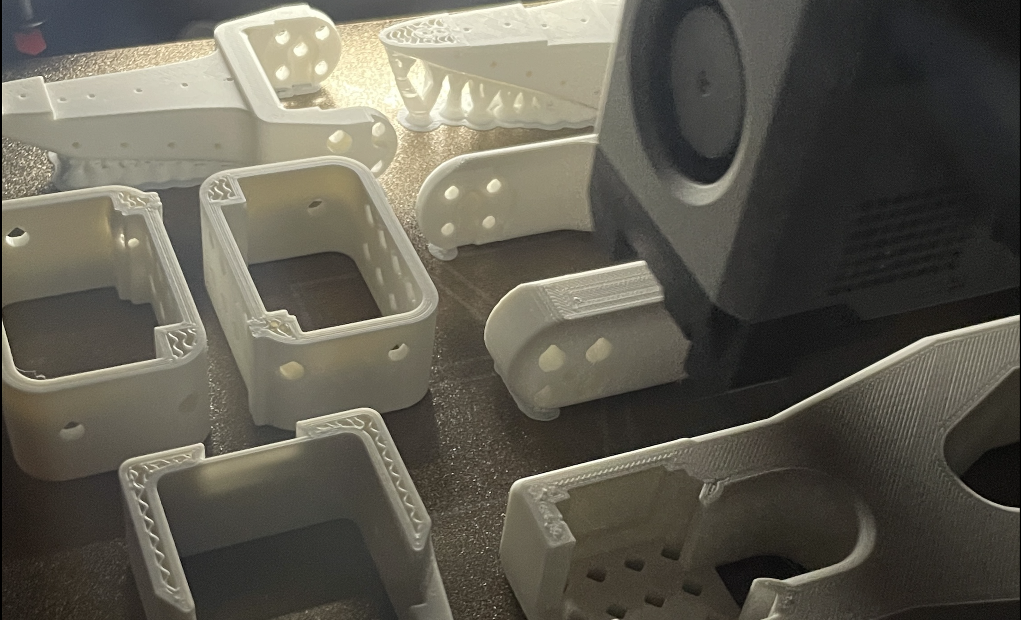
Once the parts arrived I began the process of 3D printing the rest of the required components that make up the arms. You can find the STL files here used for each of the arms. Be sure to select the right files that best align with your 3D printer.
The time it took to print each of the arms was around ~24 hours, so total almost 2 days using the Bambu Labs P1S with standard matte PLA filament.
Software Setup
With the hardware ready, the next step was setting up the software environment. The SO-ARM100 uses LeRobot, HuggingFace's robotics framework. Following the documentation, I started by creating a fresh conda environment and installing the necessary dependencies:
conda create lerobot python=3.10
conda activate lerobot
Next, I cloned the LeRobot repository:
git clone https://github.com/huggingface/lerobot.git
Before proceeding with assembly, you need to identify which USB ports each arm would use. LeRobot includes a utility script that makes this process straightforward:
python lerobot/scripts/find_motors_bus_port.py
The script walks you through connecting and disconnecting each USB bus adapter to determine its unique port. After testing both adapters, I identified the following ports:
- Leader Arm:
/dev/tty.usbmodem58FA1025271 - Follower Arm:
/dev/tty.usbmodem58FA1024401
Now once the ports were identified, I updated the configuration file found at lerobot/common/robot_devices/robots/configs.py to reflect the correct port assignments. This ensures the software can properly communicate with each arm during operation.
Motor Configuration
Before assembling the physical arms, each servo motor needed to be configured with a unique ID and proper settings. This process involved configuring 12 motors total—6 for each arm. Note that removing the leader arm gears is not required but recommended, I left the gears in the motors to save time as I felt that it would also improve teleoperation stability.
Each motor in the daisy-chain communication system requires a unique ID from 1-6. Using LeRobot's configuration script, I programmed each motor individually using the following:
python lerobot/scripts/configure_motor.py \
   --port /dev/tty.usbmodem58FA1024401 \
   --brand feetech \
   --model sts3215 \
   --baudrate 1000000 \
   --ID 1
This step gets repeated interactively for all 12 motors swapping out the port and ID depending on which arm motor is currently being configured.
The motor mapping follows this pattern for both arms:
- Motor 1: Shoulder Pan
- Motor 2: Shoulder Lift
- Motor 3: Elbow Flex
- Motor 4: Wrist Flex
- Motor 5: Wrist Roll
- Motor 6: Gripper
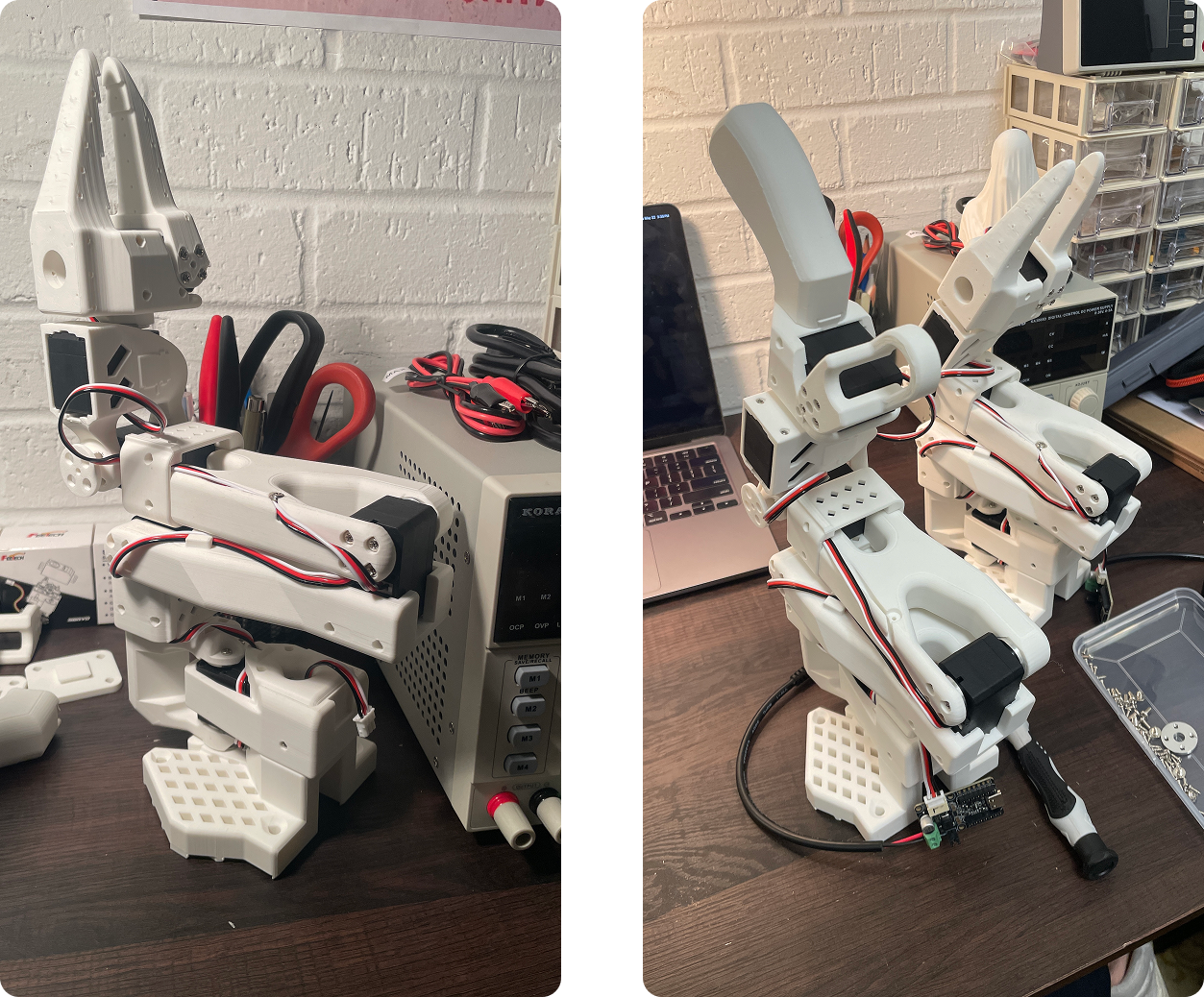
Assembly Process
The SO-ARM100 documentation provides detailed step-by-step instructions with reference images for each stage linked here, the repo docs are somewhat clear but if you would like something more in-depth Phospho AI provides a great walk through for the follower arm. The steps to assemble the leader arm is almost identical except for the end-effector which is designed to be like a hand controller. See the original documentation here for those steps.
Each arm took approximately 1-2 hour to assemble, with the first arm taking a bit longer as I familiarized myself with the process.
Calibration Process
With both arms assembled, the next step was calibration—ensuring the leader and follower arms have matching position values when in identical physical positions. This synchronization is essential for accurate teleoperation and allows neural networks trained on one SO-ARM100 to work on another. This was the first time I ran into any issues, but thankfully with some finessing it was a pretty straight forward process.
The calibration process involves moving each arm through three specific positions while the system/script records motor values to a config file in the local .cache directory:
- Zero position - Arms fully extended and aligned
- Rotated position - Joints rotated to specific angles
- Rest position - Arms in a natural resting pose
I started with the follower arm calibration:
python lerobot/scripts/control_robot.py \
   --robot.type=so100 \
   --robot.cameras='{}' \
   --control.type=calibrate \
   --control.arms='["main_follower"]'
Calibrating the follower arm didn't give me any issues, but when I ran the calibration for the leader arm this error was thrown: Wrong motor position range detected for gripper. Expected to be in nominal range of [0, 100] % but present value is -84.61538696289062 %
The leader arm gripper motor was reading -84.6% instead of the expected 0-100% range, indicating the gripper was positioned outside its calibrated limits during the calibration sequence. The pictures in the documentation showed the leader arm gripper being "closed" so wasn't entirely sure what was going on.
So after consulting with some thinking machines, it seemed the best thing to do was to just delete the calibration file in the .cache directory and try again with gripper in a neutral, mid-range position for all three calibration poses. This time, both follower and leader arm calibrations completed successfully without errors. Not entirely sure what was going on but could have be due to the gripper being over-rotated in its fully closed state and throwing off the calibration.
Testing & Teleoperation
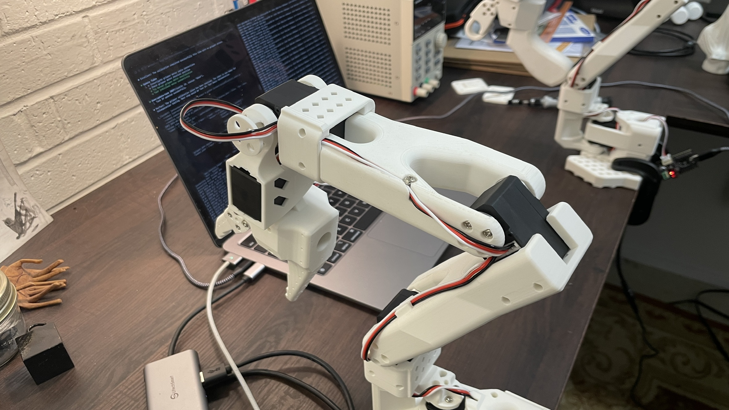
With calibration complete, it was time for the moment of truth, testing the teleoperation system. This is where the leader arm's movements would be captured and replicated in real-time by the follower arm. Note that I've anchored both arms to my table for testing as they will fall over if not secured down.
This is the command that starts the teleoperation between the Follower and Leader arms:
 python lerobot/scripts/control_robot.py \
    --robot.type=so100 \
    --robot.cameras='{}' \
    --control.type=teleoperate
Both arms connected successfully, and I could see frequency readings in the console:
INFO dt: 3.01 (332.8hz) dtRlead: 1.49 (671.5hz) dtWfoll: 0.03 (31957.1hz) dtRfoll: 1.49 (670.2hz)
The ~330Hz overall frequency indicated smooth communication, and I could feel the follower arm responding to my movements of the leader arm. For the first 20 seconds or so, everything worked exactly as intended—smooth, responsive teleoperation with minimal latency but then it would crash with the following message: ConnectionError: Read failed due to communication error on port /dev/tty.usbmodem58FA1024401 for group_key Present_Position_shoulder_pan_shoulder_lift_elbow_flex_wrist_flex_wrist_roll_gripper: [TxRxResult] There is no status packet! meaning that the connection was lost! After some digging around online, I discovered this was a known issue documented in a GitHub issue.
The problem "seemed" to be cable strain when the robot started in the reset-position. Which interrupted the daisy-chain communication between motors. I'm not 100% if that was the issue, but repositioning the follower arm to a more cable-friendly starting pose (zero) the connection error vanished and both arms somewhat demonstrated smooth, responsive control with the leader arm movements accurately replicated by the follower arm shown below.
One of the unique aspects of this build was using my custom MCP (Model Context Protocol) server called Dawn alongside Claude Code for project management and documentation. This represented one of my first experiences integrating AI assistance into a hardware project workflow.
Appendix: Project Management with Dawn MCP Server
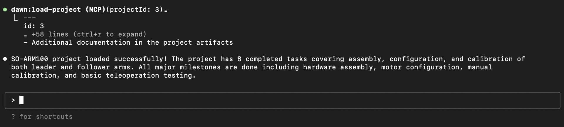
Dawn is a project management system I developed that integrates with Claude through the MCP protocol. It allows for:
- Task creation and tracking with status updates
- Project artifact (document) storage and organization
- Time tracking and project analytics
- Integration with AI workflows that are MCP clients
For the SO-ARM100 build, I created a dedicated project in Dawn that tracked:
Tasks Completed (8 total):
- Assemble follower and leader arms
- Configure motor ports and IDs
- Perform calibration sequences
- Troubleshoot gripper and communication issues
- Test teleoperation functionality
Artifacts Created (3 total):
- Configuration Reference: Port assignments and technical specs
- Project Overview: Complete project summary and goals
- Troubleshooting Guide: Documented solutions for common issues
I'll be doing a full write up in the future dedicated to Dawn and how I've been using it for other non-robotics projects.